Tuesday, January 19, 2010

My Roubo, part 9

(Go back to part 8)

Now that major construction is complete, time for fine details, starting with flattening the top. But first, I had to take care of some maintenance resulting from earlier rough-planing. When I planed down the leg glue-ups, I took off some good size chunks of fully-cured glue drips and squeeze-out. Those chunks bit back, taking sizable nicks out of the freshly crowned iron in my transitional plane.


Here's the nicked iron. That'll take some work on the 80-grit sandpaper to remove.

Which reminded me, I had modified a cheap plastic-handled chisel some time ago specifically for glue removal. I don't care how much this gets beaten up.


I hacksawed down the length of the handle to make it lie flat across a surface and rounded the corners to prevent gouging.


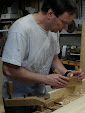
Removing the dried glue from the top with the chisel. These are the seams from gluing up the six sub-assemblies.

After restoring the blade in my transitional jack, I rough-planed the top. I started by chamfering the front and back edges to prevent spelching, then took a couple passes traversing directly across the grain. I switched to several passes of diagonals, first from one side, then the other, then changed to the jointer.


Making a diagonal pass from one side with the jointer.


I made a series of pencil lines back and forth across the top prior to jointing down the length. They're just visible here.

I made several overlapping passes down the length of the top, eyeballing the flatness and checking for wind with aluminum angle-iron winding sticks. When the pencil lines were gone, I was done. Finally, I made one pass with the smoother. Total time: about an hour.


Could I have gotten it flatter? Probably, but this was my first time ever doing this, so I figured it's best to quit before over-working it. If I find it's not good enough, I can take more passes.

Now for the planing stop. This is a 12"-long 2"x2" block that slides in a friction-fit through-mortise in the benchtop. Tap it from below to raise it for planing a piece pushed against it, push it back down when done. This is one of the fast and simple work-holding features of this bench.


Working on the through-mortise.

And now a brief word on safety from the Society for the Preservation of Toes: remember that large wooden constructs are dangerously heavy!


This lovely color on the knuckles of my toes the result of laying the bench on its back to work on the bottom side of the mortise. I tipped it back toward me, then couldn't control the load. It slipped out of my grip and the back edge landed across my toes.

Fortunately I had laid a board on the floor to provide a space to fit my fingers when righting the bench. That caught the brunt of the impact, preventing a serious crush injury. My wife asked me later if I made up any new words. I said no, I just used the ones I already knew.

Once the pain had subsided enough to continue working, I finished the bottom side. I started seeing spots as I hoisted it back upright. Won't be doing that any more!


The planing stop in place. Getting a consistent friction-fit on a 12" length is time-consuming. Start fat and plane it lightly in sections, testing the fit repeatedly.

As a final step, I lightly chamfered all the edges of the top with a block plane. Next I'll make the leg vise.

(Continue to part 10)

Saturday, January 2, 2010

My Roubo, part 8

(Go back to part 7)

Time to do the mortises in the top.


Mortising the top by boring and chiseling. A completed mortise is visible at the lower right. This is where the larger brace comes in handy; it's definitely a lot of work. One thing that helps is to work ambidextrously, switching crank arms when one tires.


Checking the floor of a mortise. Run this gauge all over to make sure there are no high spots.

Remember when I said I lusted after a nice big Lie Nielsen shoulder plane? I did some shopping at one of their hand tool events last month. When my wife asked how much I had spent, I just told her she didn't need to buy me any Christmas presents this year.


Tuning the shoulder of a leg tenon with an LN medium shoulder plane. This joint is big enough to warrant their large plane, but most of the work I'll be doing will be more to the medium scale.


Tuning up a mortise with some of my other LN purchases: planemaker's floats. These are like rasps on steroids, and come in both push and pull tooth configurations. I'll be using these to make the wooden molding planes from Larry Williams' spectacular DVD.


Test fitting the base to the top. The base weighed in 75 lbs., so I definitely want to minimize the fidgeting about with it. I got my son and one of his buddies to help me stand the top on the scale; it came in at 135 lbs., so the total is 210 lbs. A little light for this bench, but beefy enough. The leg vise will add another 10-15.


Time to drawbore the legs to the top. Setting a stop on the bit for a 5" depth.


Kerfing-in a leg shoulder for a closer fit.


Cutting off some oak stock for more pegs. I'll use the rest of this slab for the leg vise. I picked up a bunch of this stuff several years ago at the local lumber company, where they were selling it off the surplus pile for something like 25 cents a board foot.


Dropping one end of the top onto the base.


The final drop. I managed not to injure myself wrestling this thing around.


Here's that out-of-square leg. I chose to deal with it by placing the mortise to set one edge proud, where it can be planed down.


For those wondering if there's a place in the manly woodshop for the wife's delicately scented candles, the answer is Yes, definitely! They're great for waxing up pegs and plane beds to reduce friction. Other than that, they're just a fire hazard.


Pegging the top to the base. Per Chris' suggestion, I didn't glue these joints. If I ever want to move this bench out of the basement, I can drill out the pegs and remove the top for easier handling. The tension in the drawbored pegs is enough to hold it together.


Planing down the corner of the leg.


Finessing the leg with a smoother to be coplanar with the front edge of the top.


And finally! The assembled bench up on its feet. Happy New Year!

The remaining details: flattening the top, drilling the dog holes, adding the leg vise and planing stop, and dressing some of the sharp edges. I'll be going the wonder-dog route instead of an end vise, since I already have one. In the Winter 2009 issue of Woodworking Magazine, Chris said he doesn't use the crochet much, and it sometimes gets in the way. So instead I'll put in a horizontal dog hole. That will act as an end stop for pieces held in the leg vise.

(Continue to part 9)

Friday, January 1, 2010

My Roubo, part 7

(Go back to part 6)

The last step before assembling the base is to attach the hardware for the leg vise screw.


Drilling the pilot holes for the wood screws.


Screwing it down. These are long beefy screws.

The first step in drawbored assembly is to bore peg holes in the side of the mortise. Then insert the tenon and mark the hole positions with a brad point bit. Remove the tenon, re-mark the hole positions 3/32" closer to the shoulder, and bore the holes. When a peg is driven in, it follows the slightly offset path to hold the tenon in place like a spring pin.


Boring the peg holes in a leg.

For these holes, I used my Spofford brace, which I acquired recently from one of the antique shops in Amherst, NH for about $15. It's marked "Fray & Pigg"; according to the Sydnas Sloot page on these braces, Pigg parted company with Fray before 1866, so these markings date it to the period 1859-1865. This tool was made about the time Lincoln was President, during the Civil War. After some 150-odd years, it works like a dream. The cup handle and chuck are dead-on-axis, and the clamshell chuck has a dead-simple positive grip. Except when I need the torque of a brace with a larger throw, this has become my primary tool for boring, light, fast, and easy to handle.


Assembling the first joint. The alignment pin is an individual Sears Craftsman pin for about $9, since they didn't have the Companion set that Chris Schwarz recommends.

As soon as you peg one of these, you realize deep down at the cellular level, this joint is SOLID. My mortise and tenon skills still need a lot of refinement to get a close fit, but this technique makes up for any deficiency as far as structural integrity is concerned. The glue isn't really necessary.


Seems obvious in hindsight, but you should bore the holes for both stretchers before assembling the first one! Otherwise you get into the potentially difficult position of boring into a partially assembled joint with large, awkward pieces.


Boring the offset holes in a stretcher tenon.

I bored and dry-assembled the rest of the base before pegging any more joints, then pegged them all at once. This is the moment of truth. All the little inaccuracies will conspire at this point. But the base went together well, mostly square with no twist to the stretchers.


Trimming the peg ends flush.


The assembled base positioned for tracing around the leg tenons, for mortising the top.


The one most obvious issue that will require some work: the front right leg is slightly out of square in relation to the front stretcher, so there is a gap at the end of this straightedge. This means it will be slightly out of alignment with the top.


Structural test. Result: SOLID!

The next thing will be to mortise the top for attaching the base.

(Continue to part 8)