The next step was assembling the frames with drawbores.

Driving riven pegs through a dowel plate to size them.

Boring through the mortise for the peg.

Spinning the bit backward to mark the hole position in the tenon.

Marking the offset hole position just 1/32" or so closer to the shoulder.

Boring the tenon.

You can just make out the offset crescent of the tenon hole inside the mortise hole. The slight gap of the tenon shoulder will draw up tight once the peg has been driven in.

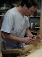
Driving in a peg.

Glued up and checked for square. Drawboring doesn't allow for much adjustment, so you need to do a good job squaring up the shoulders ahead of time.

Trimming the pegs before final flushing with a chisel.

Cutting the horn off a stile.

Planing the horn endgrain down flush with the adjacent rail edge.

Planing the joint face down flush.

The frames resting on the case.
This was where I realized my first construction mistake. I had sized the rails and stiles exactly before joining them, so that the widths and lengths all added up to the total case width, carefully squaring them up.
However, small errors in squareness conspired against me. The case was about 1/16" out of square to the left. The frames were about 1/16" out of square to the right. So they were two opposing parallelograms. Put together, the result was 1/8" out of square. After all that care, that would be too much of an error. Any adjustment in positioning just made it worse.
The problem was that I had sized everything to theoretical shapes, not to the actual shapes present. Had I left the rails a little wide, I could have trimmed them down exactly to match the case. But since I had already taken them down, there was no material left to do this. Lesson learned: leave the outer edge of the frame oversize, then plane down to the exact case shape.
To fix this, I glued narrow strips to the outside rail edges. Yes, I put wood back! Once it was dry, I flushed the strips down to the rail faces, then planed them down to exactly match the case as I should have done originally.
The next step was making the leg assemblies. These were essentially frames like the doors, with drawbored mortise and tenon joints.

The first leg unit after driving the drawbore pegs.

Closeup of a corner drawn up tight.

Completed legs after trimming and flushing the pegs.
Now I realized my next mistake. I wanted to have a small oak baseplate on each side underneath to attach the leg hinges. The plywood bottom was not sufficient to hold the screws. I had intended to house them in a partial groove in the sides along with the plywood. However, I had forgotten to do that when I glued up the case.
My solution was to add a stopped groove to the inside front and back after the fact. Instead of a full groove in the side, since I was using oak, I formed wide tenons to accept long grain tenons.
The next question is, how do you fit a piece wider than the inside dimension of the bottom into the stopped grooves? Answer: sliding wedges. You know, the magical stretching board!
I cut each baseplate on a long diagonal and carefully planed the cut edges so they would form a good edge joint. The diagonal meant that this was mostly a long-grain joint, so should glue up good and strong. That way I could fit one wedge in place, then slide the other one into place with glue applied.

Chiseling out the stopped groove in the back piece on the underside of the case. Yeah, this is as awkward as it looks.

An oak baseplate cut diagonally. You can see the long-grain tenons and matching mortise slots on the left. The upper end slides into the stopped groove. The opposing wedge slides into the matching stopped groove at the lower end.

With the upper wedge in place, the lower wedge loosely in place to show how it will slide in. With glue and clamps, that diagonal seam closes up invisibly.
From there, a variety of small detail steps.

Planing the top back edge to match the slope with a block plane.

Planing down the thin backer strips for holding the acrylic in the door frames.

Pre-drilling the screw holes in the strips.

With stain and two coats of satin polyurethane spar varnish applied, everything carefully stacked in place before installing any hardware. The clamps act as feet to hold the legs straight up.
(Continue to part 4)


No comments:
Post a Comment
Note: Only a member of this blog may post a comment.