The bench screw I ordered from Woodcraft is a finely-machined piece of German steel, but the handle they sell with it is just a large dowel with cheap plastic endcaps. Completely unworthy. So I made a real handle like the one Chris Schwarz made for his.
The handle is made by planing the corners off a squared-up length to form an octagonal cross section. Then those corners are planed down to a hexadecagonal section, until it fits loosely in the eye of the vise screw. This is a simple way to make approximately round lengths without a lathe.

This piece of scrap left after ripping the leg vise face to width is perfect for the handle. Trimming it to length on the bench hook.

Ripping it down to square.

This operation shows off the simple versatility of the planing stop. With the piece resting on a corner in a pair of long V-blocks, I bumped the stop up high enough and went to work with the block plane. It's quite fun and satisfying to do. I've found that I love chamfering edges with this plane, so now I'm a chamfering fool!

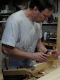
Boring holes for cross pegs in the ends of the 16-sided handle.
I used the ring trick to keep the bit level as I bored the holes. That's my wedding band riding along the middle of the bit. Sighting down on the bit, I could see that it was square to the handle diameter, but I couldn't see if it was level. By watching to see if my ring walked up or down the bit as I cranked the brace I could tell if was out of level, up or down. Just don't drop your ring and lose it in the shaving on the floor!

The completed leg vise with parallel guide and handle, and a steel drawbore pin in the guide.
I wanted to carve the year into the vise the way Bob Lang did on Chris' bench, but a little experimentation on some scrap showed that my carving skills are woefully inadequate, especially in oak. So I'll save that for another day.
Since I didn't want to tie up my drawbore pin in the vise, I made an oak pin with a handle. We'll see how it stands up over time. Chris said he went through several wooden ones before switching to a steel pin.

Boring the hole in the handle.

The wooden pin in place in the parallel guide.
The leg vise does have its quirks. One is that as you open it up and run the screw out, the bottom edge starts to jam against the floor. I've seen pictures of several roller setups on other leg vises to deal with this, and I suppose trimming a little off the bottom edge would help. But I found that giving a little upward tug with each revolution does the job.

I bored a storage hole in the side of the vise face to hold the pin and provide a handle for lifting. You can see the first placement for this hole along the screw axis, but that turned out not to work so well, so I plugged it.
Time for a little troubleshooting. After lifting the end and swinging the bench around a few times, I noticed that one leg was shifting in its mortise, despite the drawbored pegs. Naturally, this was the one with the leg vise, which needs to be a dead flat joint to avoid stamping marks into the workpiece being held in the vise.

The leg has shifted by a good sixteenth, leaving the peg ends proud.

Back in position after some gentle persuasion with a deadblow hammer.

Examining the joint from below reveals the problem: a sloppy mortise with a big gap. Fortunately, the track for the sliding deadman makes it accessible for repair.

The fix: I drove a small wedge into the gap and trimmed it flush with a chisel.
If this joint continues to move, I'll bore a hole down from the top and pin the tenon on that axis.
The next task is to make the sliding deadman.
(Continue to part 13)


You're running down the home stretch Steve. It's really looking great!
ReplyDeleteTHANKS for the ring trick; very nifty technique!
Hmmmm.... if I can rotate the workpiece and drill those vertical holes on a horizontal axis, this trick will be even more helpful.